

“Scroll down for photos and comprehensive description.” Czechmate FOR SALECzechmate N1NFSingle.
Item specifics
| Used |
| “Scroll down for photos and comprehensive description.” |
| Make: | Czechmate |
Single engine six place turboprop experimental aircraft project with tooling
This aircraft was originally manufactured as a 1977 Beechcraft Baron 58 TC serial #TK46. It is currently registered to me as as an experimental single turbine model Czechmate, N1NF.
I purchased it at a lien auction in 1989. The aircraft was a complete and undamaged BE58TC and the engines were partially disassembled. I received the proper FAA chain of title. The original owner, whom had purchased it new, had disappeared. It was later discovered that he was deceased. The airframe has only 1531 hrs TTSN with no damage history. It was in very good condition other than having slightly deteriorated paint, interior and windows. It has the factory corrosion proofing option (all interior wing and fuselage surfaces were zinc chromate primed before assembly).
I was operating an aircraft salvage business at the time specializing in parting out undamaged Beechcraft twins. I had previously worked as a mechanic at a Beech factory owned service center and had closely followed the development of the 2 Beech factory prototype single engine turbine powered Lightnings designated as Beechcraft model 38P in the early 1980s (see photos and info below). These aircraft were essentially production model Pressurized Baron airframes that were modified and converted to single engine turboprop aircraft. The Beech Travel Air and Baron models had evolved from the single engine Bonanza product line and a large percentage of the airframe components are interchangeable.
Build:
I stored the airframe in the back of my hangar and started compiling parts and components to build my own improved version of the single turbine. I spoke with a retired Beech engineer that was involved with the factory prototype and to Mike Smith (of Smith Bonanza speed mod and Smith Propjet fame) whom had resurrected one of the two prototype Lightnings (and owned the salvaged remains of the other). I purchased an ex military Pave Eagle airframe (similar to a BE36 Bonanza but with GTSIO-520 w/375HP). I evaluated and copied the structural components from the forward keels of it to support and close out the nose wheel well and add integral engine mount attach points to my airframe. The monocoque nose structure that supported the nose gear was to be removed.
When the Czechoslovakian built Walter engines became available in America I purchased a 601D with logs. It is a free turbine reverse flow turbo prop that is very similar to the Pratt and Whitney PT-6A and also very reliable. The Walter 601D has 750 HP. It was primarily used on the twin engine non pressurized 19 seat Turbo Let Eastern Block commuter airliner. The Walter does not have enough excess bleed air to pressurize the large cabin of a Baron without performance degradation so I felt that it was the ideal engine to mate to the non pressurized and much lighter 58TC. The Baron has mechanical actuated landing gear with many rods going through the pressure vessel. I also preferred the large cargo door that the TC has instead of the small aft door utilized on the P model. The 58TC and 58P airframes are very similar to each other and have many differences from the rest of the Baron family. The important differences from 58P/TC models and all other Barons are listed below.
The 58TC/P has:
-extra forward (5th) wing attach point for high speed shear strength with added fuselage carry through structure. (Similar to BE60 Duke)
-larger tail plane and elevators than most models.
-higher "never exceed speed"
-higher gross weight (6200 lbs vs 5100-5500 lbs)
-More fuel capacity (192 gallons)
-stronger landing gear utilizing components from the BE60 Duke
-Heavier duty wheels and brakes also from BE60 Duke
-additional external longitudinal structural straps on belly that tie the three wing carry through structures together.
I removed all of the original Baron nose structure back to the forward cabin bulkhead. The Baron fuselage utilizes the same internal longitudinal hat rail structures in the sides of the fuselage as a Bonanza. These are the main nose supports on the Bonanza that are integrated to the engine and nose gear support structure. I extended these channels 10" forward of the cabin interior bulkhead with doublers and utilized them as firewall supports and engine mount hard points. I extended the rest of the fuselage stringers in the same manner and fabricated a fire wall flange. The firewall was fabricated and installed at the same station as the Lightning factory prototypes. The Bonanza series utilizes a cradle mount supported by the forward keel structure that extends aft to the main spar carry through structure. I utilized the beefed up components from the front end of the salvaged Pave Eagle to tie the engine mount frame to the keels in addition to the four hard points on the firewall. This allows for the large Oxygen bottle and electrical components to be mounted in the accessible area aft of the stainless firewall and forward of the cabin interior bulkhead. All of this structural work has been completed.
I utilized machined cone shaped bushings pressed in to the solid aluminum hard points mounted behind the firewall with the mating engine mount fittings bolted to them. We then suspended and secured the Walter turbine engine in the desired position to fit and spot weld the engine mount tubes and supports in place. A transfer fixture was fabricated to facilitate fabricating a rigid jig fixture to finish welding the engine mount/nose gear support frame in. After the mount and engine were re-installed we formed a cowling plug to fabricate the molds on the aircraft with. (See pics below). The front of the cowling was fitted with close tolerances to the spinner bulkhead. I designed an internal induction plenum with a particle separator to pressurize and reverse the induction air into the rear of the engine. This induction system is similar to the aftermarket performance enhancing pitot style inlets used on the King Airs. The plenum interior cross section area is increased to slow the air before redirecting in to the rear engine air inlet. This plenum is made of carbon fiber reinforced with core material.
The cowling was manufactured with pre-impregnated carbon fiber. It was built in multiple components and vacuum cured in an oven. It has honeycomb reinforced stiffeners. It is of top quality and is very strong. It is designed for easy accessibility. The top forward cowl utilizes four quick release larches from a Beech King Air and machined tapered line up pins. It has mini NACA inlets in the front and mini louvers on top to prevent heat build up and paint blistering while running on the ground. The forward bottom cowl has an internal induction plenum and is easily removed with four internal bolts (also similar to King Air). The aft top cowls are hinged on top to a section of Beech wing spar cap extrusion similar to a Bonanza. They are held closed with three Hartwell latches on each side of the same type as the Baron nose baggage door. The lower cheek cowls are structural and permanently affixed. They are attached to the the front cowl mating surface and give additional support to the front of the nose wheel tunnel/keels. The induction inlet lip was designed to utilize a Piper Cheyenne heated deice boot. The cowling flows and fits well and is very strong and light. It was fabricated to production aircraft standards and designed to maximize performance and give easy accessibility to the engine. It can be completely removed in minutes by one person using one tool or easily opened for preflight with no tools.
The left side NACA inlet on the forward lower cowl ducts to the oil cooler that is vented out through the shark gills in the check cowl. The identical inlet on the right side provides air flow to the bleed air cabin heat exchanger plenum that is manually controlled for cabin heat and defrost. It ties in to the existing factory installed controls and cabin heat/defrost ducting. It is controlled with a variable bleed air flow valve and an iris valve that controls the flow through the heat exchanger for temperature control. The pitot engine inlet pressure is contained between the front cowl carbon fiber bulkhead and a stainless baffle that locks in place in a channel attached to the opening aft side cowls.
5 blade reversible certified Avia Propeller with electric deice.
Smooth clean lines viewed from above (or any angle). All control surfaces and tail planes are not installed but are included.
The wings are the original factory BE58TC wings with the nacelles removed. The nacelles were bolted in place over the flush riveted wig box sections and leading edges. We fabricated new leading edge sections and used flush patch methods to obtain the leading edge profile and flush patched the holes for the fuel lines and screw holes in the top wing skins. Wikipedia falsely states that the wings on the Lightning prototypes were from the BE36TC Bonanza. They are not-they are modified Baron wings the same as these. They may have been pulled from the production line prior to engine nacelle installation. The BE36TC utilizes the same shape tip extensions but does not have the extra 5th wing attach points nor do they have the extra structure and fuel capacity of these wings.
The deice system valves, controls and plumbing are retained and BE200 King Air outboard wing boots will fit these wings perfectly.
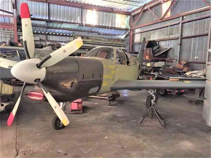
The aircraft was moved outside for these pictures. The Horizontal stabilizers and all flight controls are on shelves inside and are included. All are in excellent condition and in primer.
All new BDS thick smoke tinted windows and windshield were professionally installed by Doug Kelley. The upper fuselage skin from the windshield to the firewall was hand formed and heat treated to properly mate to the top cowling. The original factory skin was tapered to a size that would not line up correctly to the required cowling height.
The wings are in epoxy primer ready for top coat. The fuel cells were deteriorated and have been removed. New fuel cells are not included.
Most of the fuselage rivets have been replaced with flush type. I was planing to fair all of the top and side skin overlaps and paint the aircraft silver.
The carbon fiber cowling system has been fitted but the latching mechanism has not been installed yet.
The prop, spinner and bulkhead are complete and in good condition. Prop OH is recommended.
Prop deice timer is included.
The factory installed windshield alcohol deice system was retained. The pump and reservoir are mounted behind the firewall behind the flush access door in this picture. The gill type cowl outlets are for the carbon fiber oil cooler plenum outlet. They are built into the structural cheek cowl. The area was masked off and primed (it is flush with cowl and will look clean when painted. A new oil cooler with a King Air Vernatherm temperature regulator is installed. The small round hole above the wing root leading edge is for a flush mounted wing ice inspection light. This was removed from the outboard side of the nacelle.
The carbon fiber nose gear doors have been manufactured but are not installed. They are flat with core material to stiffen them. The original actuating mechanisms are utilized.
A Kieth products electric air conditioning system similar to the type used in an Aerostar has been fitted and tested. The system mounts to a shelf behind the aft cabin bulkhead and is accessible through the large access panel on the left side that only P and TC models have.
One of the features that makes this such a desirable aircraft for a turbine conversion besides the high Vne, high gross weight and large fuel capacity is the large vertical fin and rudder with adjustable trim. Compare this to a Bonanza.
The TC and P models utilize heavier duty landing gear components from the BE60 Duke. It also has the secondary down locks on the mains. These features allow for a higher gross weight (6,200 lbs) than all of the other Barons.
Wheels, brakes and tires are all new. The insides of the gear doors have been ceramic coated with a product resembling chrome. All of the landing gear components have been removed and the insides of the wheel wells have been painted with Jetglo Matterhorn white. The gear has been stripped and repainted and has new seals installed. The gear rigging has been completed.
This fiberglass covered foam plug was fabricated on this airframe to manufacture the cowling molds with light weight, heat tolerant, high strength pre-impregnated oven cured carbon fiber.
Top cowl mold curing in place in my hangar.
Finished molds are included with sale of aircraft
Modified power quadrant with prop pitch control on left, fuel condition lever on right and power lever with brass knuckle type beta/reverse lift gate. Original control cables are utilized along with the factory friction lock. I have new knobs for prop and condition lever that match the power lever grip.
The engine mount will need to be removed and powder coated. There is some finish work required on the stainless baffling. The wood boards are temporary cowl door props. The finished product should get gas discharge cylinders fitted. The factory installed high capacity oxygen bottle is installed on top on a shelf behind the large removable upper firewall panel. The lower access panel on the right covers the electrical bay where the relays and voltage control unit is installed.
This is the electric firewall fuel shut off valve that mounts in a separate compartment behind the firewall on the lower right side. It is accessible from an external hinged flush mounted access panel.
Lower forward inlet cowling showing induction plenum installed
Aft end of lower forward cowling. Small plenum on left is for oil cooler. The one on right is for cabin air heat exchanger. This assembly is removed with four internal attach bolts that attach it to the mating bulkhead in a similar manner as a King Air cowl. There will be a cannon plug required if inlet lip heat is installed. The inlet is sized the same as a Piper PA31T Cheyenne II for availability.
Picture showing cowling molds being fabricated on this airframe
Picture showing current condition and configuration. I can assist purchaser with disassembly and transport.
Power quadrant
Air conditioner components. The axial fan is a condenser fan that is typically mounted in the left nacelle with the condenser on a P Baron. I utilized it as an evaporator fan in this aircraft. The pac unit is from a Kieth Products system that was in an Aerostar. This system has been mounted on isolators and tested in the aircraft.
The electro linear actuator on other side of the autopilot servo operates an air inlet door that opens when the air conditioner is turned on. The aircraft still has the Factory installed KFC200 flight control system.
The outlet duct on top is the factory installed unit that is connected to the aft interior bulkhead. I installed the lower exhaust louvers for the condenser fan cooling air outlet.
This is the linear actuator controlled condenser cooling inlet scoop that opens when the air conditioner is turned on. It is a modified version of the condenser scoop that is used on the top of the left nacelle of the P Baron. It has been fitted and tested.
This is the AC overhead interior plenum that is mounted to the ceiling of the cabin. It is a modified Kieth products piece from an after market system for a Piper Aztec. It extends to just behind the pilot seats.
This picture is a close up showing the finish work on the top of the wing where the nacelle was removed. The small holes in the top of the spar caps will be filled with rivets or screws in the same manner as when used Baron spars were installed in Beech T34s in accordance with AMOC STC.
New professionally installed BDS thick windshield and Windows are installed all the way around.
Flush access door on left side aft of firewall showing windshield alcohol reservoir and GPU receptacle. This aircraft can be pre-cooled on the ground with aux. power unit.
Shark gills are oil cooler plenum exhaust that were copied in carbon fiber from later bonanza cheek cowls.
Flush riveted skins where lower firewall hard points are installed inside of the main longitudinal hat rail members.
Picture showing later Baron nose baggage door Hartwell latch temporarily fitted to side cowling. There are three on each side.
Grimes ice inspection light that mounts above the leading edge of the left wing.
Picture of the interior of the nose wheel well close out taken from below looking forward.
Left side of firewall. Removable access panel to autopilot computer and remote gyro. The aircraft is set up for two large 24 volt batteries stacked in front of the firewall. The extra battery improves the weight and balance.
Shows left side of the inertial particle separator plenum with the induction plenum turning bucket removed. A linear actuator opens the two large iris valves simultaneously actuating a deflector door preventing ice or rain water from entering the engine. This system is very similar to the inertial particle separator installed on the new TBM 930.
This picture shows the end of the left auxiliary diagonal engine mount leg that attaches near the engine mount ring to the nose wheel well tunnel keels. It also shows the oil cooler mounted to the inside of the left structural cheek cowl and the oil cooler air plenum.
This photo is of the right side of the firewall showing the ammeter shunt, dual battery relays and the starter/generator relays.
Devcon battery connectors are installed for dual batteries. The large cannon plug is for the starter generator and other two are for engine wiring harness.
Left side of engine. The exhaust stack cutouts have not been made yet.
Forward structural bulkhead with removable induction turning bucket in place.
Picture with cowls removed. The top front, lower front and hinged top aft cowls can be removed by one person in minutes with one 7/16" inch socket and ratchet.
Instruments included. There is an auxiliary mounting pad on the accessory housing that will run an Airborne 412CW pressure pump to operate the KI256 Flight director and the pneumatic deice boots system that is factory installed. There is also a pad that will accept a standby alternator.
Other instruments included and left panel
Center panel with engine instruments, new EI fuel totalizer and factory fuel gauges.
Exhaust stacks and fairings
These longitudinal external straps are only used on the 58TC for added strength. They extend from the forward 5th wing attach point carry through structure aft past the front spar carry through structure to the rear spar carry through structure.
These new retractable 6" grimes lights have been wired and fitted to the lower outboard wings.
Retractable lights mount near tip extensions in only spot with no fuel tank. They double as speed brakes.
Strobes with added alternate flashing Grimes recognition lights.
Oscillating Grimes clear belly beacon and nose gear mounted taxi light.
Engine mount fixture/jig and line up fixture for locating firewall hard points included with sale.
Complete original six place interior can be configured as club or forward facing. Writing table included. Aft seats fold up and middle seats are easily removed for cargo configuration.
Extra "super soundproofing" has been numbered cut and fitted.
All flight controls are included and in excellent condition
2 fuel strainer filter assemblies are included. One is from a Walter 601D Turbo Let and other with impending by bass annunciator switch is from Bell 205A1 commercial Huey.
Extra new surplus Whitaker firewall shut off valves are included.
4 ea constant duty submersible fuel pumps included. Two are required and the other two are spares.
The 58 P and TC model are the only Baron models that use the submersible constant duty "in tank pumps". These are ideal for the Walter free turbine engine. It is much more desirable to push fuel rather than pull fuel up to the engine. Many experimental turbine installations use a firewall mounted electric boost pump that effectively keeps the fuel lines, boost pump, fuel strainer, fuel selector valve and numerous fittings at "negative" pressure. The Walter fuel control unit will not function properly if any air is introduced into the fuel system. The effect is cumulative. I know of many flame out type engine failures caused by not using submersible fuel pumps. It is virtually impossible for this type of failure to occur using this system. That is the reason that almost all production turbine aircraft use this type of pump configuration. The flow and pressures from these pumps are adequate for either pump to operate the engine. The pumps have built in regulators that can be adjusted by an overhaul facility to the exact recommended pressure. These pumps are rated for constant duty. The Walter engine will operate without boost pump with some possible power loss but it is not recommended. This aircraft was built with the proper fuel line diameter. There is a factory installed cable actuated selector valve in each main wheel well and a cross feed line that runs through the cabin. I retained these valves and reconfigured them to utilize the cross feed line to transfer fuel from one wing to the other. The operation is simple and has many advantages. Take off and initial climb is performed with the left and right valves selected on and both boost pumps on. The fuel travels to a "T" fitting with a check valve mounted to each of the "T" inlets to prevent back flow. An electric firewall mounted shut off valve is mounted to the "out" side of the "T". This gives boost pump redundancy if one pump was to fail. After initial climb one of the fuel valves can be selected to the "transfer" position with the respective boost pump switch remaining on (other pump remains on at all times). The fuel transfer rate is slightly higher than the engine fuel consumption rate. When an inline pressure switch detects "no transfer" then the boost pump operating in the transfer mode is selected off. All of the remaining useable fuel is now in one tank. There is never a need to switch back and forth between tanks and it is not possible to run a tank dry with fuel remaining in the other tank using this fuel management method. I designed and installed this system in another similar aircraft and it functions flawlessly. If one wing gets heavy the transfer pump can be turned off until balance is obtained. If the transfer pump fails the valve can be selected from transfer to on and balance can be obtained by selecting the other pump off. The fuel balance can still be maintained independent of electrical power. This is not possible in some single turbine production models. The TBM uses an electric servoed valve that automatically switches back and forth constantly to maintain balance.
These factory installed submersible fuel pumps are rated for constant duty and can be adjusted to the exact Walter recommended output pressure specification. They mount inside the bottoms of each wing and are easily removed.
Propellor deice timer is included along with two new surplus Generator Control Units (Piper Cheyenne type)
High speed antennas included
Pulse Control unit for wing tip recognition lights included
Extra parts and tooling included. There are enough of the metal parts included for two more aircraft.
Extra carbon fiber lower forward cowl internal induction plenum is included along with the fabrication mold pictured
The two halves get bonded together and bond inside of bottom cowl.
This is a photo of a different aircraft that was built in my shop under my supervision utilizing my tooling.
Side view of the same aircraft
Info From old ad for this Current date: 2018-08-08